|
#1
 06-08-2012, 06:25 PM
|
||||
|
||||
 GUIDE: How to Test and Use an LCD's LED backlights
 Hey Technibblers! Testing LCD backlights is commonplace for many techs and repair shops. With the industry moving to LED backlighting technologies instead of CCFL (Cold Cathode Flourescent bulbs) you may want a way to test the LED backlights before declaring a need for a replacement screen. My experience has shown that the LEDs are rarely bad, nor the controller that lights them. It usually boils down to the LCD cable, motherboard or a SMD fuse issue. So, without further delay, here's how you can light an LED backlight screen without it being connected to the computer. WARNINGS:
Pre-apology: The only pics I have at the moment are ones I have soldered leads onto. I wasn’t planning on making a guide/tutorial.. I was just making a broken LCD “Demo” for customers that come in.. a conversation piece to hang on the wall. I was also going to rip the LED strips out of screens I get to make 12v low-voltage garden and pathway lights. On the back of every LCD panel you will see a PCB (Printed Circuit Board) with electronic components located under the “Do Not Touch” plastic. We need to find the side that has the ribbon cable that goes to the LED backlight (Left or Right side) and fold the plastic back so that you have access the LED controller and contact pads. My screens are broken, so I just ripped ‘em off. 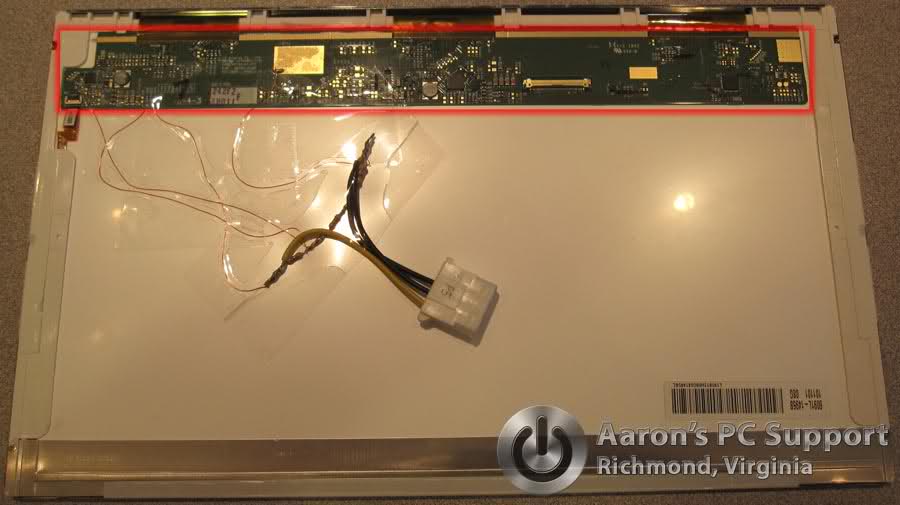 You are looking for: • Common, Ground, or (-) negative. This is the easiest to find because common is generally all over the board and is truly "common" for the entire board. The LCD Ribbon cable connector is always grounded. Big square pads of copper should be ground. • An LED voltage supply pad or point… a bit harder to spot but should be going to a small fuse; usually labeled F1, F2, etc. • The EN or ENA, BL_ON, LEDON or ENAB pin/pad. This basically tells the LED controller to turn ON or OFF regardless. Supply with +5V. • PWM pin/pad (Pulse Width Modulation) allows the Motherboard to control the brightness. Usually the MOBO supplies this pin with a “pulsed” signal that flashes the LEDs very fast (Rate determined by signal) to allow for brightness control, power savings (efficiency), and prolongs LED life by reducing the duty cycle of the LEDs. I have found that most screens have an exposed copper pad for testing during/after manufacturing for each one of these. There is *generally* no need to solder to the side of chips or components. 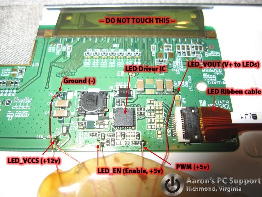 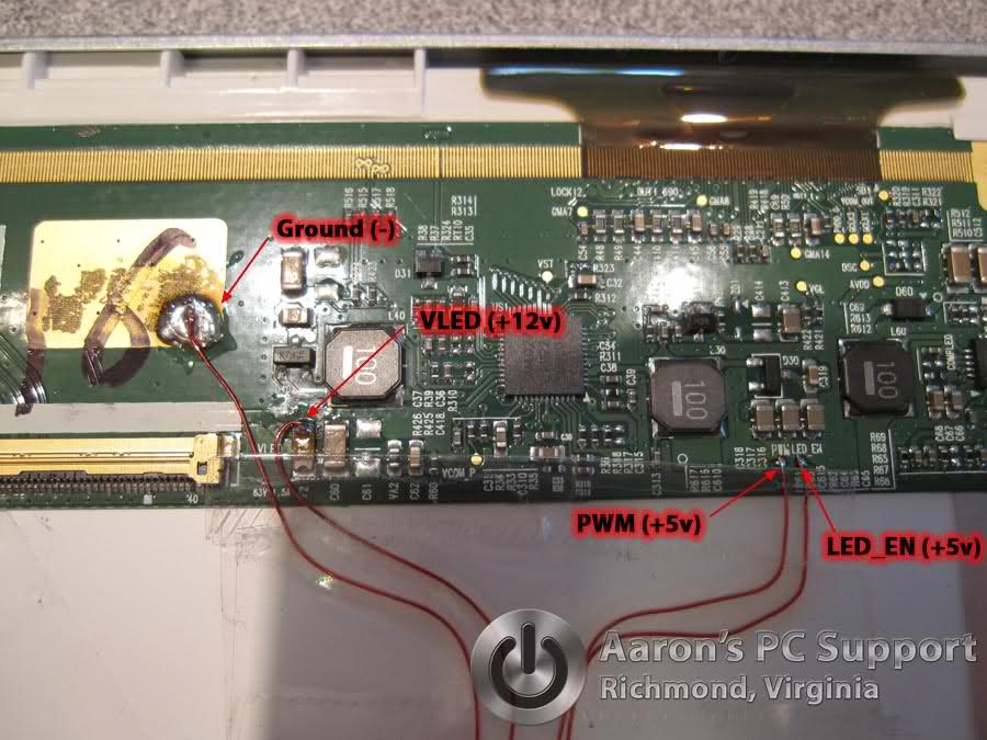 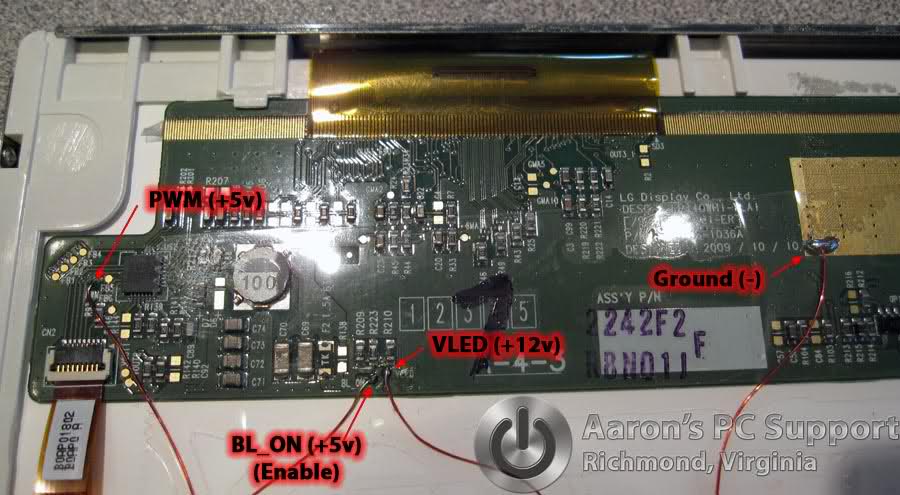 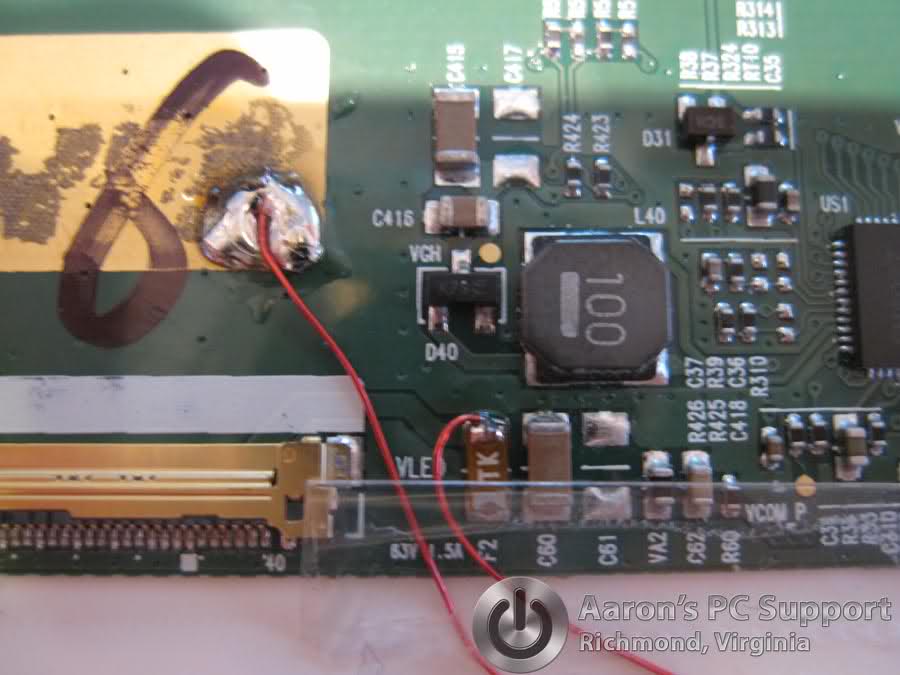 I made a simple voltage divider using 3 resistors to get 5v from the 12v supply I am using. We will use 12v to supply the LEDs and circuit. The 5v will be used to bring the LED driver’s inputs HIGH. You *should* be able to use 12v in place of the 5v, but you really take a chance on damaging the LED driver IC. Some are able to take up to ~35v, but some don’t. Be safe and use the resistors. Anything between about 1.75 to 7v should be safe and will suffice to turn the LEDs on. 1/4 watt resistors will do fine for this low-power project. If you need to know how to make a voltage divider check here (Really easy): http://hyperphysics.phy-astr.gsu.edu...ic/voldiv.html
You should have light! 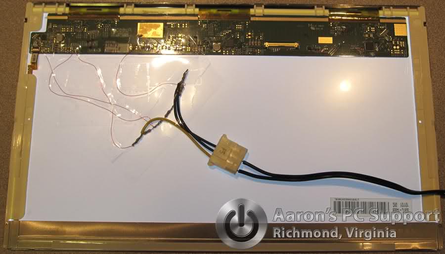  Two Wire LED backlight configurations: Netbooks such as the Dell Inspiron Mini 10 and possibly others may only have two wires going to the LED backlight instead of a multi-wire ribbon cable. There is generally no PWM input, but simply an “ENABLE” or LED_ON pad. Supply this with a +5v and it should light. I am assuming that these screens are using voltage regulation to control brightness instead of PWM but I can’t really say for sure. Once you know the above information testing these things becomes child’s play! With a screen attached to its cable and the laptop on you can now test the LED backlight circuit:
Taking it a step further, while powered by the laptop you could jump a wire from the LED_VCCS to the PWM and/or ENABLE pin if they are not getting power… preferably with a 5v source. Even though I made a voltage divider for each of my screens I did test each one with a straight 12v to the ENABLE pin and PWM pins and they worked just fine for 15-20 minutes each until they were unhooked. I still recommend a 5v source for these to be safe. Hope this helps my fellow techs out there! Good luck!
__________________
 Aaron Heidlebaugh Computer Technician / Owner www.AaronsPCSupport.com 804-307-4465 (Call or Text) Laptop LCD repair | DC Power Jack Repair | Virus Removal Desktop Repair | Hardware | Software | Troubleshooting Last edited by phaZed; 06-08-2012 at 06:39 PM. Reason: Added picture. 
|
|
#2
06-08-2012, 07:21 PM
|
||||
|
||||
|
Very nice break down of what is what on the board and showing how to feed power to each circuit, but its a lot of work considering you have to do this with EACH screen that comes into question.
Wouldn't it be better to create a cable that will fire the LED from the LCD cable connector ? Something like this : http://www.lcdparts.net/WHSDetail.aspx?ProductID=3826 Allows you to start the LED on the LCD and you can either buy their light testers or make your own, the pinouts on the connector would give you guidance how to do it. This way you do all the work once and not have to do this every time.
|
|
#3
06-08-2012, 07:30 PM
|
|||
|
|||
|
Quote:
Even while I already knew how to do this, there's no way I'm going to do it to test a screen, nor would I suggest it to anyone. Build or purchase a cable to test the LEDs. You could easily build a couple of different cables to be compatible with nearly every screen out there.
|
|
#4
06-08-2012, 08:09 PM
|
||||
|
||||
|
NYJimbo,
Yes, a tester cable could be handy if you were interested in only testing the backlight circuit which I find is rarely bad. It will not help you narow the problem down to the laptop's cable or motherboard. I had soldered leads onto these LCD's only because I was testing and wanted to use the LEDs in a separate project (Not repair). The practical knowledge is in the guide. Once you know what pins do what, and what voltage each need to have, you can test the LED backlight with nothing more than a multimeter while the unit is plugged into its laptop and you can determine what is wrong. No special $22 cable needed 
__________________
Aaron Heidlebaugh Computer Technician / Owner www.AaronsPCSupport.com 804-307-4465 (Call or Text) Laptop LCD repair | DC Power Jack Repair | Virus Removal Desktop Repair | Hardware | Software | Troubleshooting Last edited by phaZed; 06-08-2012 at 08:14 PM.
|
|
#5
06-08-2012, 08:19 PM
|
||||
|
||||
|
Quote:
Likewise, I think its a safe bet that most of the techs here are not really comfortable with small SMD circuit soldering. The idea of making a LED testing LCD cable was so you could just snap it in place, send power and know in seconds if the LED firing circuitry was functioning.
|
|
#6
06-08-2012, 08:26 PM
|
||||
|
||||
|
Quote:
There is NO soldering required unless you want to use these for some other "fun" purpose, as is what I am doing. Using a multimeter with the LCD plugged into it's laptop you can touch Ground and: PWM ENABLE V+ to see what they read. No soldering, and within 15 seconds you have an answer. Certainly, a cable such as was listed would indeed do the same thing for testing the LEDs as I have done with the soldering.
__________________
Aaron Heidlebaugh Computer Technician / Owner www.AaronsPCSupport.com 804-307-4465 (Call or Text) Laptop LCD repair | DC Power Jack Repair | Virus Removal Desktop Repair | Hardware | Software | Troubleshooting
|
|
#7
06-08-2012, 08:45 PM
|
||||
|
||||
|
Quote:
I was just thinking a schematic or something on how to make a LCD cable/power "thingy" would be better for the average tech to use on a daily basis. Not trying to start some kind of ugly back and forth on your technique or anything. Props for your electronics knowledge. 
|
|
#8
06-08-2012, 08:57 PM
|
||||
|
||||
|
Sorry the guide disappoints

__________________
Aaron Heidlebaugh Computer Technician / Owner www.AaronsPCSupport.com 804-307-4465 (Call or Text) Laptop LCD repair | DC Power Jack Repair | Virus Removal Desktop Repair | Hardware | Software | Troubleshooting Last edited by phaZed; 06-08-2012 at 09:27 PM.
|
|
#9
06-08-2012, 09:01 PM
|
|||
|
|||
|
Quote:
I made some edits to that post, then ended up deleting it. It's a better guide than anything I've contributed in the past few years. I'm too lazy to post a diagram of my testing tools. 
|
|
#10
06-08-2012, 09:20 PM
|
|||
|
|||
|
For me the value was actually phaZed description of where to test not necessarily how to test. I haven't had to test one of these yet, but now at least I feel better prepared.

|
 |
|
|


 Linear Mode

